First of all, a shout out to cwlongshot for proofreading this post.
This thread is on the removal, disassembly, and servicing of the individual components of the fuel pump assembly on a 2006 Sportsman 700 EFI. This summer I had problems with my machine spitting and sputtering, or dying for no apparent reason, so I started researching forums for fixes and found huge numbers of people with the same symptoms. Along the way, I documented my troubles in this forum and fixed many things. Those threads, which you may find useful, can all be found through this thread:
http://www.polarisatvforums.com/for...e/19800-fixed-700-sportsman-efi-spitting-sputtering-dying-when-ridden-hard.html
Much to my amazement, when I started looking for an aftermarket fuel pressure regulator part number I discovered that nobody had found one yet. I was convinced there was a pressure regulator out there somewhere, so I started digging and eventually found one. I never did find a thread on how to service the fuel pump assembly and since I was removing it anyway, I thought it would be helpful.
Keep in mind this procedure is for my own 2006 Sportsman 700 EFI Twin Cylinder. I don’t mind helping if I can, but if you are contemplating doing this, I assume you have the mechanical ability to sort out any differences in our machines with parts/wiring diagrams.
Except for the gas gauge sender portion, these principles and/or procedures don’t apply to carburetor machines.
GENERAL NOTES:
Pumps and strainers you can use:
O’Reilly’s:
Airtex E8198 pump only – this is the one I’m removing because it was not doing well in the warmer fuel in the tank.
Airtex FS111 strainer
NAPA part numbers:
NFP P72118, pump comes with strainer, NAPA on the box but made by Carter as P72118.
Based on my threads I concluded the NAPA/Carter is the pump of choice if you have the problem where your machine gets really warm and then either dies or won’t restart when hot.
AFP E8198, pump only; by Airtex
BSH N69496, Bosch pump
DFP FE0055, Delphi pump
DFP FS0070, Delphi strainer
There are others as well.
Automotive application for fuel pump: 1992 Hyundai Sonata, 2.0L 4-cylinder.
Regulators:
PR210 Standard Motor Products, eBay and Amazon, and others
BWD 23020 Borg Warner O’Reilly’s
CRB 219679 NAPA part number
Automotive application for regulator: 1996 Jeep Grand Cherokee, 5.2L V-8
1. In order to replace the pump or strainer sock, you will have to completely remove the fuel pump assembly from the tank. The regulator and gauge sending unit can be accessed with only partial removal, but it is much easier to just take it out completely. Besides, I highly recommend replacing the strainer sock if you are this far already.
2. While you have the gas tank removed is a great opportunity to do some easy housekeeping and preventive maintenance to otherwise hard to access places. Here’s a list of things I did:
-- Replaced the spark plugs.
-- Cleaned the throttle body
-- Put foil insulation on the bottom of the fuel tank.
-- Cleaned out the fuel tank
-- Replaced the fuel filter
-- Blew out the fuel lines with compressed air, and wrapped them in foil insulation where they might be exposed to heat from the exhaust.
-- Removed the fuel rail, took out the valve core (it’s just a bicycle valve), and blew air through it. In a returnless fuel system such as this one, anything that gets past the filters will usually make its way to the end and stay there. In this case, the relief valve and possibly the right side injector.
-- Visually inspected the injectors’ filter screens.
-- Tightened up the reed assembly cover (the attachment on the top rear of the valve cover for the hose that goes to the air box).
3. Right and left references are as if you are sitting in the seat.
4. Make sure you have ventilation.
5. Unhook the negative cable from the battery.
YOU ARE WORKING WITH GASOLINE! Don’t do something that will burn your eyebrows off or we will make you post pictures of it on the forum.
GETTING THE FUEL PUMP ASSEMBLY OUT OF THE TANK:
1. Remove the front fender plastic and put the gas cap back on.
2. Bleed fuel pressure through the relief valve located at the end of the fuel rail on the right side of the machine. If you have a fuel pressure tester with a relief button, then use it. If not, wad up a paper towel around a small screwdriver and press in on the valve for a couple seconds.
The machine is clean now…I promise.
![Image]()
3. Unhook the fuel tank vent line from the little connector.
4. Remove the air box and put a rag in the throttle body
5. Remove the crankcase and belt cover snorkels and put a rag in the port where the snorkels were.
6. Unplug the 3-wire fuel pump/sender wiring harness. Pull the gas tank back an inch or so by lifting upward and backward. This allows you to remove the fuel line from the top of the fuel pump assembly, which you should do now.
7. Remove the gas tank from the machine lifting upward and backward.
-- Siphoning the gas out beforehand makes it a bit easier to handle and lessens the chance of spilling gas. If you can’t siphon it, you will need to pour it into a gas can after you have it removed. Regardless, you need to make sure you have no more than half a tank before proceeding.
8. Remove the 5 bolts holding the fuel pump assembly to the tank.
-- The 5 holes are not evenly spaced so before you remove the unit, make a mark to help you remember where the gasket goes. Not a big deal, just easier later on.
9. Pull the assembly up until the float wire is hitting the edge of the hole. You can go a little further but the float wire must be removed before you can get the rest of the assembly out.
10. Remove the clip holding the float wire pivot point in place. Make sure the pivot point is not binding and GENTLY spread the flanges just enough to pull the pivot point off the assembly, allowing you to twist the float wire out of the tank.
![Image]()
11. Pull the rest of the assembly out.
-- The strainer will make it difficult to get out. If you’re replacing it, you can cut the strainer with scissors. If you’re keeping it, it’s just plastic and will bend somewhat for you to work it out. For the price, I would replace it if you are going this deep.
REPLACING THE PUMP:
Be careful with any plastic parts on the fuel pump assembly because they can be broken if too much pressure is applied to them.
1. If you think you need to, take a digital picture to help remember the location of the parts. Or you can use this one.
My filter sock is filthy!
![Image]()
2. Remove the red and black wire from the connectors making note of which wire goes where. If you get it backwards, the pump will run backwards.
3. Remove the clamp that holds the hose to the pump between the pump outlet and the regulator inlet.
4. Note the way the bracket fits onto the mounting post and snip the zip ties holding the pump. Remove the pump outward and downward with a slight twist to help it slip out of the hose. You can remove the black plastic mounting bracket first if it makes it easier.
5. Install the new pump and hose clamp, zip tying it to the bracket and mounting post. Make it look like it did before.
6. Check all the connections in the flow. Look for cracked hoses, loose clamps, solid wire connections, etc.
7. Connect the wires. When connecting the wires, I found the spade connectors to be slightly loose. Squeeze the connectors a little tighter if they seem loose.
8. Slide the strainer over the intake on the pump. Make sure you orient it with the long end pointing in the direction of the float.
9. Installation is the reverse of removal.
REPLACING THE REGULATOR:
1. Remove the fuel pump assembly from the tank.
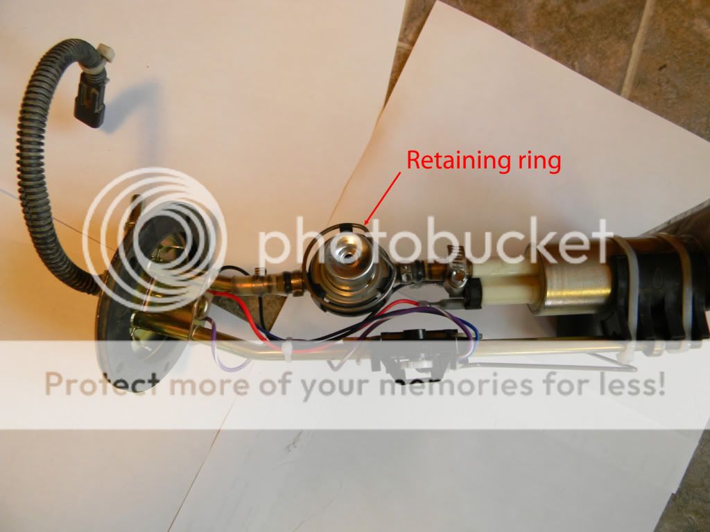
2. Remove the retaining ring.
![Image]()
3. Give the regulator a twist to break it free of the o-rings. I used channel lock pliers.
4. Carefully spread the flanges and pull the regulator out.
-- Having a helper might make it easier.
-- If one of the flanges snaps off, it’s not a show stopper but is still a pain. If it happens, I know of someone who used a castle nut just big enough to go over the barrel of the regulator and rest on the outer flange of the regulator. He then used zip ties routed through the indents of the castle nut and around the mounting pole to secure the regulator. If you come up with a better way then let us know. Hopefully you won’t have to.
The first thing you will notice is the new regulator has a vacuum reference port. That’s because this regulator is normally mounted on the end of the fuel rail in the engine bay of a1996 Jeep Grand Cherokee. The port is hooked up to the vacuum system and allows the regulator to use the engine vacuum to help pull the relief valve open, lowering the fuel pressure at idle. When the engine revs up, fuel demand increases, vacuum decreases, and the regulator increases the fuel pressure until it reaches its specified pressure. The pump far exceeds the demand of the engine so excess fuel is constantly returned to the fuel tank via the return line from the regulator. Having gone through the engine bay the fuel is warmer than when it left the tank, which isn’t what you want.
On our ATVs, we have a returnless system where the regulator is mounted inside the tank without a return line. Our fuel system is supposed to maintain a constant pressure of 39 +/- 3 psi. This regulator is a 39 psi regulator. When nothing is hooked up to the vacuum port, the regulator simply references the constant pressure inside the tank. Fuel pressure never gets adjusted downward from 39 psi because there is no vacuum to help pull the relief valve open. Therefore we have a constant fuel pressure in the system of 39 psi. Excess fuel that isn’t pushed into the system is dumped directly into the tank via the port on the small end of the regulator. I’ve talked to the manufacturer’s engineer and he says this regulator will be OK in a submersible application and should work for us.
5. Examine the old regulator to see if there’s excessive dirt or anything else lodged against the filter screen. If there is, you definitely need to replace the strainer and clean the tank thoroughly.
6. To install the new regulator, put a thin film of motor oil on the o-rings and push it into place. Again, be as gentle as possible to avoid breaking off the flanges, or worse, the whole housing.
7. Since the new regulator is 1mm less in diameter than the OEM, you will need to snip about an eighth-inch off each end of the retaining ring. Then bend it slightly smaller so it will hold the regulator tight. Install the retaining ring and you are done.
TROUBLESHOOTING A FUEL GAUGE SENDER:
The most common complaints are a constant reading at or near empty, erroneous readings (for example, shows half full when actually topped off), or the gauge showing intermittently or not at all.
The fuel gauge sender uses a variable resistor to send a signal to the speedometer. There are two sliding contacts on the pivot point of the fuel gauge sender. As the float moves up and down inside the tank, the contacts slide along corresponding tracks on a small circuit board. One track is continuous. The other track is sliced into very small sections. Those sections provide variable resistance as the contact moves up and down with the movement of the float. The resistance value is translated by the speedometer into a reading on the gas gauge.
![Image]()
Constant reading at or near empty:
1. This condition almost always means the float on the end of the wire has a hole in it and has filled up with fuel, causing it to sink to the bottom no matter how much fuel is in the tank.
-- There could be something broken or physically impeding the movement of the float wire but that would most likely result in erroneous readings.
2. Unless you can find the hole and plug it, you will need to replace the float with one of these:
Here is a link to a fuel gauge float that has been successfully used by OuachitaMtnMan.
Fits: Allis Chalmers: D10 Through D19
Replacement for D-Series Gauges
http://stores.djstractorparts.com/-s...uge/Detail.bok
3. Save the retaining clip to use with the new float.
Erroneous readings:
1. Something physically impeding the movement of the float.
2. Float wire bent where it shouldn’t be. A manufacturer defect of this nature is HIGHLY unlikely. Someone has probably monkeyed with it before.
3. One of the sliding contacts is bent or twisted, causing it to contact the wrong portion of the circuit board track relative to the float position.
4. Faulty circuit board
Fuel gauge shows up intermittently or not at all:
Check first before removing the fuel tank:
1. Power to the fuel gauge sender.
a. Hook up a meter set to DC volts on the machine side of the 3-wire fuel tank harness, leads B and C. On my machine it’s the black lead to the brown (middle) wire and red lead to the purple/white wire.
b. Turn the key on and you should get a reading of 5 volts. If there is no power and speedometer is working other than the gas gauge, there is likely something wrong with the speedometer inside because the purple/white wire comes from the speedometer. You will need to resolve that issue first.
2. If you have power coming to the harness, set your meter to continuity and hook it up to the brown wire and the purple/white wire on the fuel pump assembly pigtail. If you have an intermittent gauge, you should also shake the machine vigorously to see if sloshing the fuel around causes it to come and go. If you get intermittent or no continuity, it is worth taking the unit out of the fuel tank and checking the following:
On the fuel pump assembly:
1. Check the wires.
a. The blue wire should be connected from the circuit board to ground.
b. The purple/white wire should go from the pigtail connector, through the grommet at the top of the assembly, and connect to the circuit board.
c. Check the continuity of the blue wire, also the purple/white wire from the connector to the circuit board. They’re not likely to be broken but…
2. Check the contacts. The power for the gas gauge passes through these contacts. If one or both of them loses contact with the track, the gas gauge won’t show at all.
a. Make sure the sliding contacts are not bent or twisted in such a way that they don’t stay in contact with the tracks on the circuit board.
b. Ensure they are curved out far enough to maintain positive pressure against the circuit board regardless of the side-to-side movement of the float wire.
![Image]()
3. Once you have adjusted the contacts and checked the wiring, hook up your meter again to the tank wiring pigtail, checking the resistance between the brown wire and the purple/white wire. If all is well, you should get a reading between 6-90 ohms depending on the position of the float. You should also see your gas gauge on the speedometer.
4. Ops check the gauge.
a. Attach the wiring harness and turn the key on. Hold on to it because the pump will run for 2 seconds then quit, and could cause it to fall from wherever you placed it.
b. Test the gauge by moving the float to see if the readings on the gauge adjust along with it. Give it time…the gauge is very slow to adjust to movements of the float. Otherwise it would be constantly changing with the sloshing of the fuel.
Good luck,
Stew
This thread is on the removal, disassembly, and servicing of the individual components of the fuel pump assembly on a 2006 Sportsman 700 EFI. This summer I had problems with my machine spitting and sputtering, or dying for no apparent reason, so I started researching forums for fixes and found huge numbers of people with the same symptoms. Along the way, I documented my troubles in this forum and fixed many things. Those threads, which you may find useful, can all be found through this thread:
http://www.polarisatvforums.com/for...e/19800-fixed-700-sportsman-efi-spitting-sputtering-dying-when-ridden-hard.html
Much to my amazement, when I started looking for an aftermarket fuel pressure regulator part number I discovered that nobody had found one yet. I was convinced there was a pressure regulator out there somewhere, so I started digging and eventually found one. I never did find a thread on how to service the fuel pump assembly and since I was removing it anyway, I thought it would be helpful.
Keep in mind this procedure is for my own 2006 Sportsman 700 EFI Twin Cylinder. I don’t mind helping if I can, but if you are contemplating doing this, I assume you have the mechanical ability to sort out any differences in our machines with parts/wiring diagrams.
Except for the gas gauge sender portion, these principles and/or procedures don’t apply to carburetor machines.
GENERAL NOTES:
Pumps and strainers you can use:
O’Reilly’s:
Airtex E8198 pump only – this is the one I’m removing because it was not doing well in the warmer fuel in the tank.
Airtex FS111 strainer
NAPA part numbers:
NFP P72118, pump comes with strainer, NAPA on the box but made by Carter as P72118.
Based on my threads I concluded the NAPA/Carter is the pump of choice if you have the problem where your machine gets really warm and then either dies or won’t restart when hot.
AFP E8198, pump only; by Airtex
BSH N69496, Bosch pump
DFP FE0055, Delphi pump
DFP FS0070, Delphi strainer
There are others as well.
Automotive application for fuel pump: 1992 Hyundai Sonata, 2.0L 4-cylinder.
Regulators:
PR210 Standard Motor Products, eBay and Amazon, and others
BWD 23020 Borg Warner O’Reilly’s
CRB 219679 NAPA part number
Automotive application for regulator: 1996 Jeep Grand Cherokee, 5.2L V-8
1. In order to replace the pump or strainer sock, you will have to completely remove the fuel pump assembly from the tank. The regulator and gauge sending unit can be accessed with only partial removal, but it is much easier to just take it out completely. Besides, I highly recommend replacing the strainer sock if you are this far already.
2. While you have the gas tank removed is a great opportunity to do some easy housekeeping and preventive maintenance to otherwise hard to access places. Here’s a list of things I did:
-- Replaced the spark plugs.
-- Cleaned the throttle body
-- Put foil insulation on the bottom of the fuel tank.
-- Cleaned out the fuel tank
-- Replaced the fuel filter
-- Blew out the fuel lines with compressed air, and wrapped them in foil insulation where they might be exposed to heat from the exhaust.
-- Removed the fuel rail, took out the valve core (it’s just a bicycle valve), and blew air through it. In a returnless fuel system such as this one, anything that gets past the filters will usually make its way to the end and stay there. In this case, the relief valve and possibly the right side injector.
-- Visually inspected the injectors’ filter screens.
-- Tightened up the reed assembly cover (the attachment on the top rear of the valve cover for the hose that goes to the air box).
3. Right and left references are as if you are sitting in the seat.
4. Make sure you have ventilation.
5. Unhook the negative cable from the battery.
YOU ARE WORKING WITH GASOLINE! Don’t do something that will burn your eyebrows off or we will make you post pictures of it on the forum.
GETTING THE FUEL PUMP ASSEMBLY OUT OF THE TANK:
1. Remove the front fender plastic and put the gas cap back on.
2. Bleed fuel pressure through the relief valve located at the end of the fuel rail on the right side of the machine. If you have a fuel pressure tester with a relief button, then use it. If not, wad up a paper towel around a small screwdriver and press in on the valve for a couple seconds.
The machine is clean now…I promise.

3. Unhook the fuel tank vent line from the little connector.
4. Remove the air box and put a rag in the throttle body
5. Remove the crankcase and belt cover snorkels and put a rag in the port where the snorkels were.
6. Unplug the 3-wire fuel pump/sender wiring harness. Pull the gas tank back an inch or so by lifting upward and backward. This allows you to remove the fuel line from the top of the fuel pump assembly, which you should do now.
7. Remove the gas tank from the machine lifting upward and backward.
-- Siphoning the gas out beforehand makes it a bit easier to handle and lessens the chance of spilling gas. If you can’t siphon it, you will need to pour it into a gas can after you have it removed. Regardless, you need to make sure you have no more than half a tank before proceeding.
8. Remove the 5 bolts holding the fuel pump assembly to the tank.
-- The 5 holes are not evenly spaced so before you remove the unit, make a mark to help you remember where the gasket goes. Not a big deal, just easier later on.
9. Pull the assembly up until the float wire is hitting the edge of the hole. You can go a little further but the float wire must be removed before you can get the rest of the assembly out.
10. Remove the clip holding the float wire pivot point in place. Make sure the pivot point is not binding and GENTLY spread the flanges just enough to pull the pivot point off the assembly, allowing you to twist the float wire out of the tank.

11. Pull the rest of the assembly out.
-- The strainer will make it difficult to get out. If you’re replacing it, you can cut the strainer with scissors. If you’re keeping it, it’s just plastic and will bend somewhat for you to work it out. For the price, I would replace it if you are going this deep.
REPLACING THE PUMP:
Be careful with any plastic parts on the fuel pump assembly because they can be broken if too much pressure is applied to them.
1. If you think you need to, take a digital picture to help remember the location of the parts. Or you can use this one.
My filter sock is filthy!

2. Remove the red and black wire from the connectors making note of which wire goes where. If you get it backwards, the pump will run backwards.
3. Remove the clamp that holds the hose to the pump between the pump outlet and the regulator inlet.
4. Note the way the bracket fits onto the mounting post and snip the zip ties holding the pump. Remove the pump outward and downward with a slight twist to help it slip out of the hose. You can remove the black plastic mounting bracket first if it makes it easier.
5. Install the new pump and hose clamp, zip tying it to the bracket and mounting post. Make it look like it did before.
6. Check all the connections in the flow. Look for cracked hoses, loose clamps, solid wire connections, etc.
7. Connect the wires. When connecting the wires, I found the spade connectors to be slightly loose. Squeeze the connectors a little tighter if they seem loose.
8. Slide the strainer over the intake on the pump. Make sure you orient it with the long end pointing in the direction of the float.
9. Installation is the reverse of removal.
REPLACING THE REGULATOR:
1. Remove the fuel pump assembly from the tank.
2. Remove the retaining ring.
3. Give the regulator a twist to break it free of the o-rings. I used channel lock pliers.
4. Carefully spread the flanges and pull the regulator out.
-- Having a helper might make it easier.
-- If one of the flanges snaps off, it’s not a show stopper but is still a pain. If it happens, I know of someone who used a castle nut just big enough to go over the barrel of the regulator and rest on the outer flange of the regulator. He then used zip ties routed through the indents of the castle nut and around the mounting pole to secure the regulator. If you come up with a better way then let us know. Hopefully you won’t have to.
The first thing you will notice is the new regulator has a vacuum reference port. That’s because this regulator is normally mounted on the end of the fuel rail in the engine bay of a1996 Jeep Grand Cherokee. The port is hooked up to the vacuum system and allows the regulator to use the engine vacuum to help pull the relief valve open, lowering the fuel pressure at idle. When the engine revs up, fuel demand increases, vacuum decreases, and the regulator increases the fuel pressure until it reaches its specified pressure. The pump far exceeds the demand of the engine so excess fuel is constantly returned to the fuel tank via the return line from the regulator. Having gone through the engine bay the fuel is warmer than when it left the tank, which isn’t what you want.
On our ATVs, we have a returnless system where the regulator is mounted inside the tank without a return line. Our fuel system is supposed to maintain a constant pressure of 39 +/- 3 psi. This regulator is a 39 psi regulator. When nothing is hooked up to the vacuum port, the regulator simply references the constant pressure inside the tank. Fuel pressure never gets adjusted downward from 39 psi because there is no vacuum to help pull the relief valve open. Therefore we have a constant fuel pressure in the system of 39 psi. Excess fuel that isn’t pushed into the system is dumped directly into the tank via the port on the small end of the regulator. I’ve talked to the manufacturer’s engineer and he says this regulator will be OK in a submersible application and should work for us.
5. Examine the old regulator to see if there’s excessive dirt or anything else lodged against the filter screen. If there is, you definitely need to replace the strainer and clean the tank thoroughly.
6. To install the new regulator, put a thin film of motor oil on the o-rings and push it into place. Again, be as gentle as possible to avoid breaking off the flanges, or worse, the whole housing.
7. Since the new regulator is 1mm less in diameter than the OEM, you will need to snip about an eighth-inch off each end of the retaining ring. Then bend it slightly smaller so it will hold the regulator tight. Install the retaining ring and you are done.
TROUBLESHOOTING A FUEL GAUGE SENDER:
The most common complaints are a constant reading at or near empty, erroneous readings (for example, shows half full when actually topped off), or the gauge showing intermittently or not at all.
The fuel gauge sender uses a variable resistor to send a signal to the speedometer. There are two sliding contacts on the pivot point of the fuel gauge sender. As the float moves up and down inside the tank, the contacts slide along corresponding tracks on a small circuit board. One track is continuous. The other track is sliced into very small sections. Those sections provide variable resistance as the contact moves up and down with the movement of the float. The resistance value is translated by the speedometer into a reading on the gas gauge.

Constant reading at or near empty:
1. This condition almost always means the float on the end of the wire has a hole in it and has filled up with fuel, causing it to sink to the bottom no matter how much fuel is in the tank.
-- There could be something broken or physically impeding the movement of the float wire but that would most likely result in erroneous readings.
2. Unless you can find the hole and plug it, you will need to replace the float with one of these:
Here is a link to a fuel gauge float that has been successfully used by OuachitaMtnMan.
Fits: Allis Chalmers: D10 Through D19
Replacement for D-Series Gauges
http://stores.djstractorparts.com/-s...uge/Detail.bok
3. Save the retaining clip to use with the new float.
Erroneous readings:
1. Something physically impeding the movement of the float.
2. Float wire bent where it shouldn’t be. A manufacturer defect of this nature is HIGHLY unlikely. Someone has probably monkeyed with it before.
3. One of the sliding contacts is bent or twisted, causing it to contact the wrong portion of the circuit board track relative to the float position.
4. Faulty circuit board
Fuel gauge shows up intermittently or not at all:
Check first before removing the fuel tank:
1. Power to the fuel gauge sender.
a. Hook up a meter set to DC volts on the machine side of the 3-wire fuel tank harness, leads B and C. On my machine it’s the black lead to the brown (middle) wire and red lead to the purple/white wire.
b. Turn the key on and you should get a reading of 5 volts. If there is no power and speedometer is working other than the gas gauge, there is likely something wrong with the speedometer inside because the purple/white wire comes from the speedometer. You will need to resolve that issue first.
2. If you have power coming to the harness, set your meter to continuity and hook it up to the brown wire and the purple/white wire on the fuel pump assembly pigtail. If you have an intermittent gauge, you should also shake the machine vigorously to see if sloshing the fuel around causes it to come and go. If you get intermittent or no continuity, it is worth taking the unit out of the fuel tank and checking the following:
On the fuel pump assembly:
1. Check the wires.
a. The blue wire should be connected from the circuit board to ground.
b. The purple/white wire should go from the pigtail connector, through the grommet at the top of the assembly, and connect to the circuit board.
c. Check the continuity of the blue wire, also the purple/white wire from the connector to the circuit board. They’re not likely to be broken but…
2. Check the contacts. The power for the gas gauge passes through these contacts. If one or both of them loses contact with the track, the gas gauge won’t show at all.
a. Make sure the sliding contacts are not bent or twisted in such a way that they don’t stay in contact with the tracks on the circuit board.
b. Ensure they are curved out far enough to maintain positive pressure against the circuit board regardless of the side-to-side movement of the float wire.

3. Once you have adjusted the contacts and checked the wiring, hook up your meter again to the tank wiring pigtail, checking the resistance between the brown wire and the purple/white wire. If all is well, you should get a reading between 6-90 ohms depending on the position of the float. You should also see your gas gauge on the speedometer.
4. Ops check the gauge.
a. Attach the wiring harness and turn the key on. Hold on to it because the pump will run for 2 seconds then quit, and could cause it to fall from wherever you placed it.
b. Test the gauge by moving the float to see if the readings on the gauge adjust along with it. Give it time…the gauge is very slow to adjust to movements of the float. Otherwise it would be constantly changing with the sloshing of the fuel.
Good luck,
Stew
") Ain't it fun!
Ain't it fun!